Using the expansion options on the controller
The VanTurtle fan controller comes with multiple 2×3 pin headers (also known as dupont headers or berg connectors) that allow expanding the controller in different ways. All have a standard pitch of 2.54 mm, the same as a Raspberry pi for instance. You can optionally have these soldered on during the ordering process.
CONN: The I2C expansion header
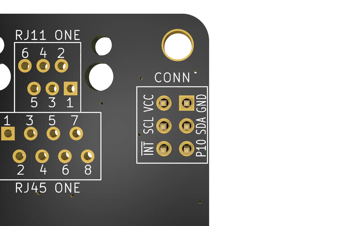
Located next to fan one, this header is intended to connect the I2C to another device. You can for instance add a temperature sensor here, or an accelerometer to measure how level the vehicle is. The 6 pins are labeled on the bottom and have these functions:
| Pin | Function |
|---|---|
| VCC | Directly connected to VCC on the screw terminal, depending on your supply should be either 3,3v or 5v. Do NOT exceed 1A on this pin. |
| GND | Shared ground. |
| SCL | The I2C clock signal. |
| SDA | The I2C data signal. |
| INT | Pulled low unless control chip sends an interrupt signal. Explained below. |
| P10 | Fan one auto temperature (AUTOHOLD) input. Pulled high unless the fan is in auto mode with the green LED on. |
The interrupt pin allows you to be notified whenever the auto temperature mode of either fan is turned on. To use it you will need to connect a 10k ohm resistor between the INT pin and VCC. Then the pin will be pulled high if the state of the auto LED changes. This interrupt is cleared if you read the input register state over I2C.
The P10 pin can be used in a similar way for fan two specifically. It’s always pulled high, unless the LED is on.
GPIO: General IO instead of a fan
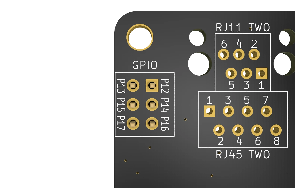
Next to the fan two plug is the GPIO header. This header is useful if you are only controlling one fan. It exposes the raw connections to the IO expander on the board, allowing them to be used for whatever you want. You could for instance show status LEDs anywhere in your camper, or detect a button press.
The pins P12 to P17 correspond to bits 2 to 7 on the input and output registers of port 1. Using the configuration register at address 0x01 you can set these to either input or output. For input, note that they have a 10k ohm pulldown resistor connected. Please refer to the documentation on I2C communication to learn more about reading or writing to these pins. Never pull more than 0,5 amps over these pins, use a relay if you need to switch more power.
I2C ADDR & PUR: I2C settings
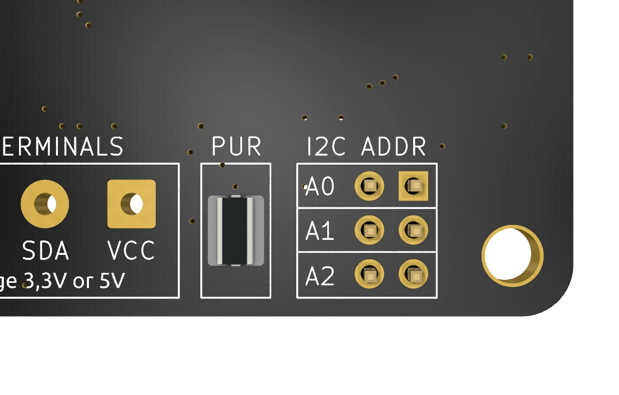
The I2C ADDR block allows you to select what address the controller should be on. More details on what pins cause what address can be found here. When looking at the back, the pins closest to the mounting hole have weak VCC applied to them and connect to the IO expander. The holes opposite are connected to ground. If you short these two in any way that address pin will be low. You can do this the nice way with pins and a jumper, but a bit of solder works as well.
I2C works by having either the leader or follower pull the line low. To be able to do that there needs to be a Pull-Up Resistor (PUR) on the same line. These resistors are present on the board but not connected by default to protect your microcontroller. There is no standard voltage defined for I2C, and sending 5v into an ESP32 will instantly fry it. If you are sure that the VCC is acceptable for your microcontroller to take on a GPIO pin you can add a little solder on the PUR pads to bridge them and get a 10k ohm pull-up to VCC.
Test Points: Debugging or IO
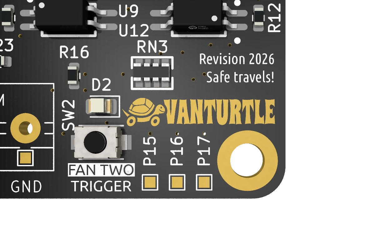
On the front of the board you’ll find 3 pads marked P14, P16 and P17. These are connected to the same wires as the GPIO pins with the same label. They can be used for debugging the outputs a little easier, or for soldering directly to the pads.
The VanTurtle logo itself is actually also a debug pad, connected to P14. The same goes for the Swedish flag on the back of the board, which connects to P07 on logical port 0. Little Easter eggs.
If you did not order the board with the screw terminals already soldered on you can use similar pads for the VCC, SDA, SCL and GND connections as well.
