Installation guide
This page will walk you through installing the controller with the fan and connecting it to your microcontroller.
Selecting wires
At a minimum you will need:
- 1x Ethernet or phone wire for each fan you’re connecting
- 4x Jumper wires to connect to your microcontroller
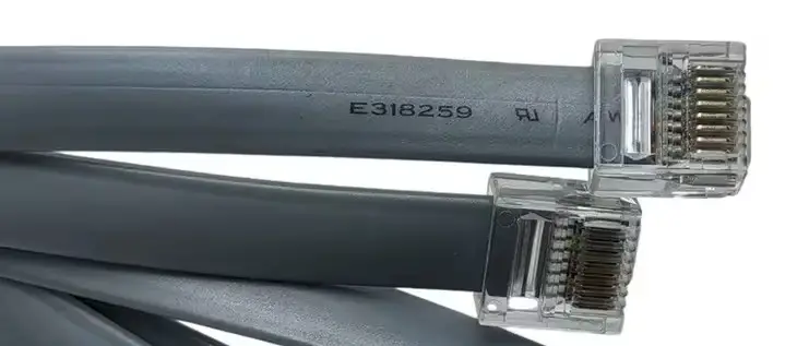
IMPORTANT: If you’re using an ethernet cable for a Deluxe fan RJ45 port you need to use a cable with a short plug. These are also marketed as a compact body or flat ethernet cable. The location of the port on the Deluxe models is such that you otherwise risk snapping off the port when you lower the fan back onto the roof. Here’s an example of a short plug:
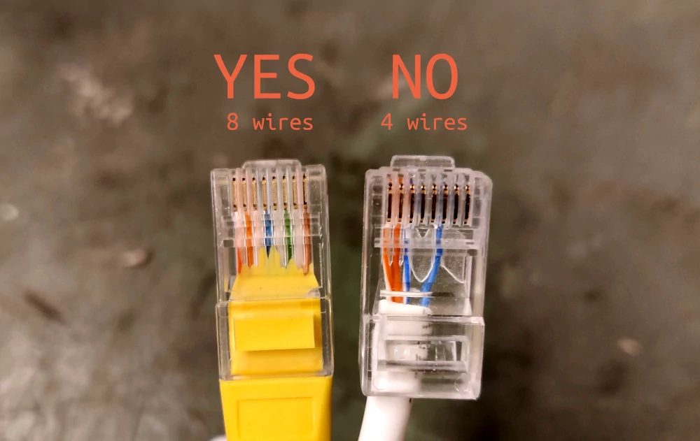
IMPORTANT: Make sure that your communication wire has all the needed conductors. For RJ45 you will need a cable with all 8 conductors, and for RJ11 you’ll need at least 4. There are many cables on the market that will fit in the sockets but because they have fewer conductors some or all functionality will not work over these cables.
Ethernet cables with only 4 conductors work for networking at slower speeds, so are often cheaper. Cables rated for Power over Ethernet are a relatively safe bet. Here’s the difference between the two: (these are to show the conductor count only, both of these plug bodies are too long to fit with the Deluxe fan!)
Installing the fan
This section is specific to the Maxxair Deluxe as we have the most experience with those. For most Plus installations you seem to be able to simply access the plug sockets when the fan is installed.
- Remove the fan from its mounting plate by getting roof access and removing the 4 retaining screws on the two long sides. Your fan should now be free of the frame of the vehicle, barring any electric wiring.
- Insert your communication cable in the RJ45 or RJ11 socket on the fan and dangle the cable through the hole into the vehicle.
- Very slowly lower the fan back in. Keep an eye on the wiring and make sure none get stuck between the edge and the fan. Screw the fan back in.
Connecting the microcontroller
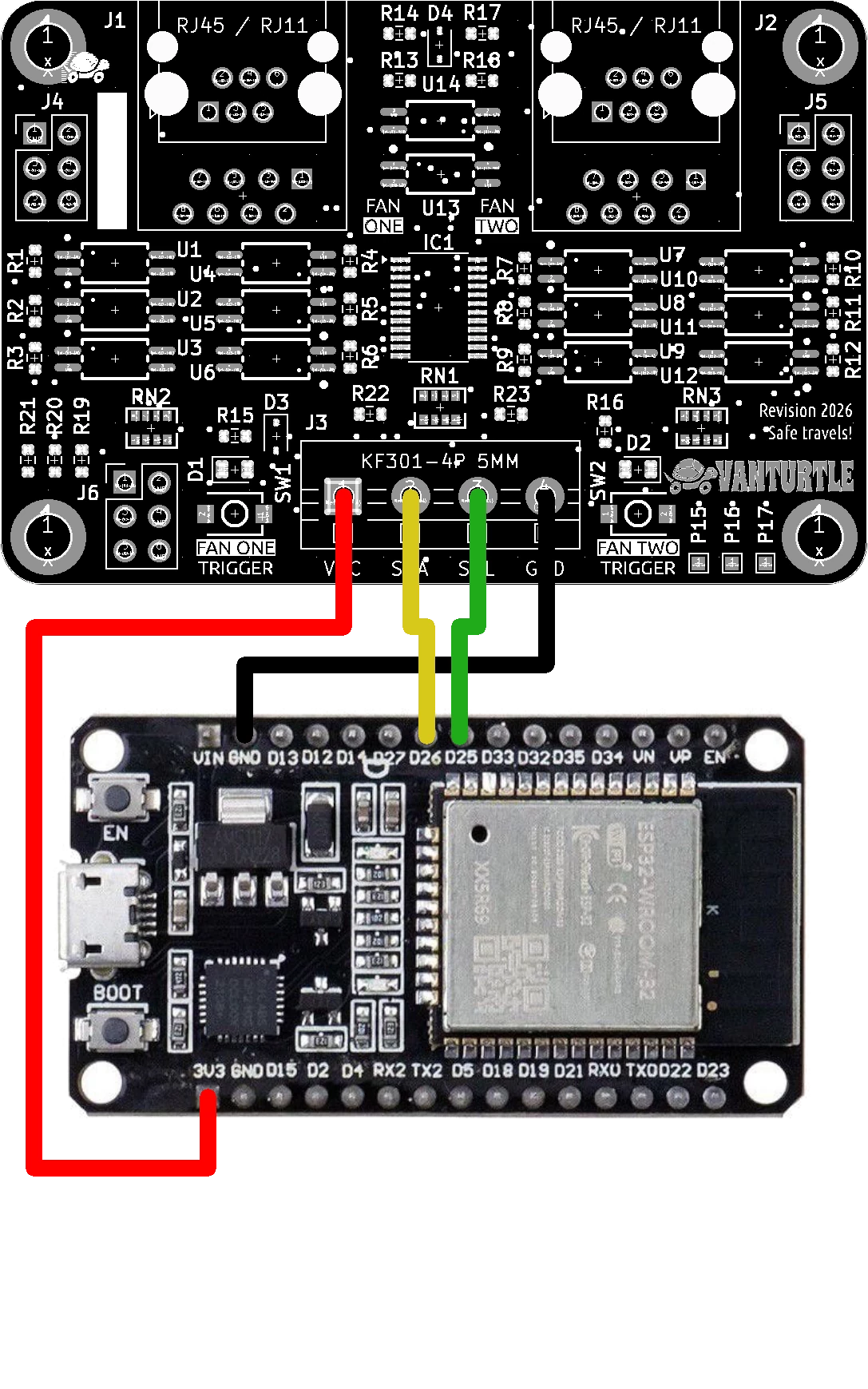
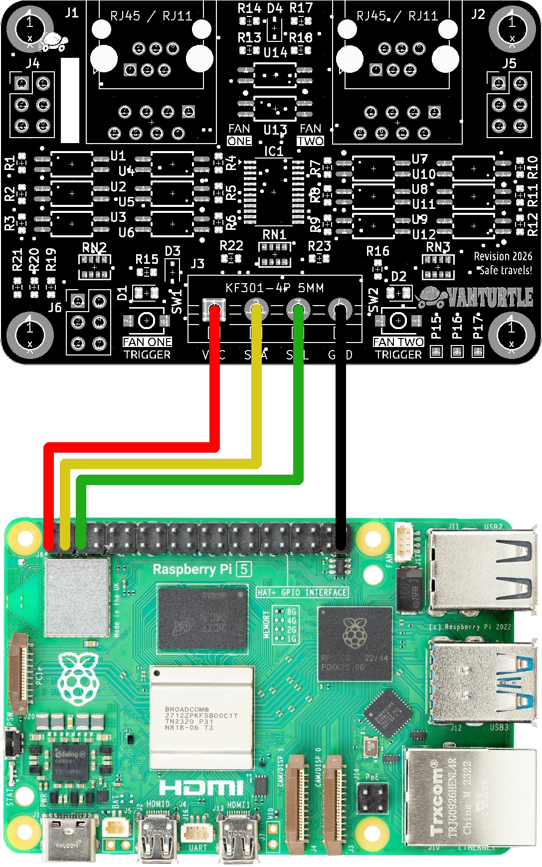
Now you just need to get the digital communication between the fan controller and your microcontroller working. You’ll need to supply 5 or 3,3 volt to VCC, connect the common GND, and connect the SDA and SCL lines to the correct pins:
The I2C bus works by having both lines be pulled up, and either end drains to make a logical 0. This means that somewhere on the line there needs to be resistors connected to VCC. Some microcontrollers can do this themselves. If yours does not the fan controller already includes these resistors as well but they are disabled by default. Refer to the documentation article Communicating with the fan controller for more details about these.
